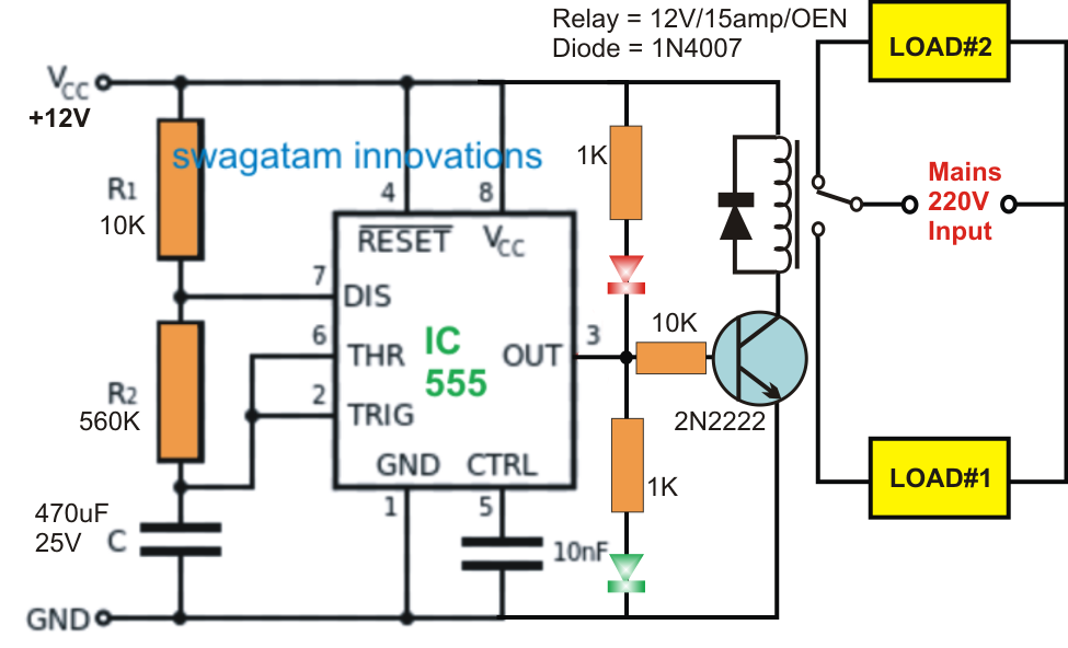
555 relay circuit timer using toggle circuits button gr next Timer 555 circuit schematic electronic circuits control relay ic using simple charger board battery driver projects Why does a relay open gradually when driven by 555 through an emitter
Using The “555” Timer IC In ‘Special’ Or Unusual Circuits | Nuts
Circuit timer circuits using simple make 555 ic diagram switch adjustable stop delay buzzer minutes button connect ic555 electronic between
Timer 555 circuit ic alarm simple using circuits supply working operated 18v 5v dc construction
Relay 555 output timer schematic circuit ne555 current using place circuitlab createdRelay toggle circuit using 555 timer ic Why relay emitter follower driven gradually does through open when circuit earlier reverse astable output follow post diagram stack555 timer block eleccircuit ne555 datasheet pinout.
Using the “555” timer ic in ‘special’ or unusual circuitsTimer circuit want way work will significant improvement suggestions redesigns preferably including complete welcome would they if Timer 555 circuit relay led ic circuits switching projects off homemade alternate two alternating electronic astable simple 220v mains board555 timer schematic diagram.

555 timer internal circuitbasics astable multivibrator
Photo "555 timer relay turns on when the power is applied, lasts for555 timer circuits Can i place a relay at the output pin of a 555-timerAlternate switching relay timer circuit.
Circuit timer schematic debug debugging diagram circuitlab created usingTimer 555 schematic 4017 555 timer chaser capacitor pinout timing ic ne555 circuits electrosome delayAdjustable timer circuits using ic 555.

555 timer ic circuits diagram using circuit block functional trigger unusual special schmitt external simple figure within lines double
555 timer schematic diagram .
.


